The Making of a
Mecanum Rover
01The Concept
I began this project because of my interest in cars, engineering and autonomous vehicles (vehicles that act on observations of their surroundings). More specifically, I wanted to build a radio-controlled (RC) car in order to examine the difficulties involved in taking a design through mechanical assembly, electrical connections and the software required to coordinate its movement.
I chose a mecanum rover (a wheeled robotic platform), where each wheel has angled rollers and is driven by a separate motor. The basic idea is that, by coordinating the directions in which the four wheels rotate, the rover can move forwards, sideways or turn on the spot. This arrangement has the advantage of supporting several types of movement, whilst requiring the wheel orientations and motor directions to agree with the movement specified by the controller (control unit).
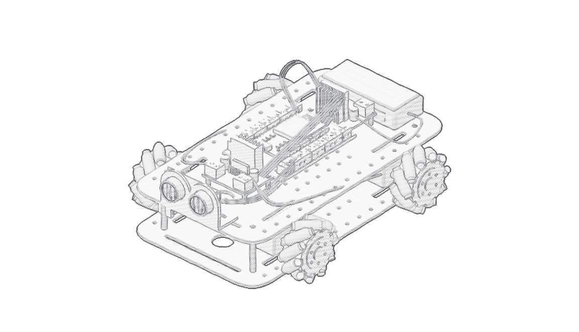
The remainder of this report is structured as follows. The electrical arrangement and components are described in Sections 2 and 3, followed by the construction procedure (Section 4). Section 5 describes the intended obstacle-avoidance method, Sections 6 and 7 present the demonstrations and limitations, and Section 8 discusses three possible extensions.
This report distinguishes the constructed platform and recorded demonstrations (qualitative observations) from a systematic evaluation of control performance.
02The Diagram
For the rover to move, an instruction from the ESP32 (microcontroller) must determine the current supplied to each motor. I have used two L298N boards (motor drivers) to connect these two functions, following the arrangement in the supplied Robot LK circuit: the ESP32 provides the control signals, whereas the motor drivers switch the motor supply in response to those signals.
Each L298N contains two full bridges (bidirectional switching circuits), so that one board can control two direct-current (DC) motors independently. I therefore use one board for the front motor pair and another for the rear motor pair, providing four independently controllable outputs. This arrangement has the advantage of using the same driver type for all four motors; however, the drivers introduce a voltage drop (voltage loss), which reduces the voltage available to the motors and dissipates energy as heat, as specified in the L298 datasheet.
I have included the two 18650 cells (rechargeable batteries) and their holder as the rover’s power source, alongside a common ground (reference potential) for the control electronics. The distinction matters because the modules must interpret their signals relative to the same reference, whilst the supply voltage required by the control electronics must still be considered separately from the motor supply.
I have also included the front HC-SR04 (ultrasonic distance sensor), whose trigger input initiates a measurement and whose echo output reports the duration of the returning signal. The arrangement describes the functions of these connections, whilst the pin assignments, regulated supplies and echo level shifting (voltage conversion) must be verified for the fitted boards before it can serve as a complete wiring specification.
Overall, I have separated the electrical arrangement into sensing, control and motor-power functions, so that each connection can be understood in terms of the measurement, instruction or supply that it carries.
03The Components
I have organised the materials into two groups: the components used to construct the rover, and the workbench equipment (reusable tools) used to prepare the assembly. The quantities and approximate costs below follow the original materials list, where a quantity of one refers to a purchased item or pack, rather than necessarily to a single fitted component (e.g., the motor-driver pack contains four boards, of which two are fitted).
Car Kit Materials
| Component | Qty. | Est. £ |
|---|---|---|
| Mecanum car kit Metal chassis, four wheels and TT geared motors | 1 | 32 |
| L298N motor drivers Four-board pack; two boards fitted | 1 | 10 |
| ESP32 + expansion board Microcontroller and accessible terminals | 1 | 15 |
| 18650 battery holder Holder for the rechargeable cells | 1 | 7 |
| EFEST lithium-ion battery Battery purchase as listed | 1 | 18 |
| M3 nylon mounting hardware Black spacers, screws and nuts | 1 | 7 |
| Adhesive board spacers 0.49-inch insulated supports | 1 | 8 |
| HC-SR04 distance sensors Ultrasonic ranging modules | 1 | 8 |
| Distance-sensor holder One mounting bracket | 1 | 5 |
| Subtotal | £110 | |
Workbench Materials
| Component | Qty. | Est. £ |
|---|---|---|
| Silicone soldering mat Reusable work surface | 1 | 10 |
| Soldering iron kit Iron and preparation tools | 1 | 17 |
| Breadboard jumper wires Prototyping connections | 1 | 9 |
| Light sensor / learning components Listed for introductory Arduino work | 1 | 6 |
| Male-to-female wires Connections between modules | 1 | 6 |
| Subtotal | £48 | |
I have retained the quantities, estimated prices and product references from the original materials list, whose rounded budget is approximately £160 (£110 + £50). Note that the light-sensor entry in that list links to a component assortment (a mixed pack), so I have preserved that distinction in the table.
This distinction allows me to separate the cost of the rover’s components from the cost of equipment that can be reused in subsequent projects. It has the advantage of making the two types of expenditure explicit, whilst both still contribute to the initial budget (approximately £160). In summary, the itemised estimate is £158, comprising £110 for the rover materials and £48 for the workbench materials.
04The Rover Conception
I constructed the rover in successive stages, beginning with the motor connections and ending with the assembled chassis (supporting frame), electronics and battery holder. This section describes the preparation of the motor leads, the wheel arrangement and the two-deck structure, after which I explain the front distance sensor and the measurement on which the intended obstacle-avoidance method depends.
Motor Connections and the Drive Base
First, I learnt to solder by preparing the leads (connecting wires) for the four geared DC motors, attaching the black and red leads to their respective terminals (connection points). Soldering provides a direct electrical connection, whilst the small terminals leave limited room for handling the joint. Hence, preparing the motors also required me to consider how the leads would be routed without pulling on those connections during the subsequent assembly.
Next, I mounted the motors on the lower metal deck (drive base) and fitted the mecanum wheels to their shafts. Recall that each mecanum wheel has angled rollers, so the movement produced by the four wheels depends on their combined directions of rotation. This has the advantage of permitting lateral movement (sideways travel), whilst an incorrectly oriented wheel or reversed motor connection can cause the resulting movement to differ from the requested movement.
A Two-Deck Mechanical Assembly
Once the drive base had been assembled, I fitted a second metal deck above it using standoffs (spacers), creating a separate mounting surface for the electronics. This arrangement has the advantage of keeping the motors below the control components, whilst making the motor leads less accessible after the upper deck is fitted. The assembly order therefore affects how easily a connection can later be inspected or replaced.
I then mounted the ESP32, its expansion board (accessible terminals) and the two L298N boards on the upper deck, followed by the battery holder. Keeping these components on the same deck produces a compact assembly, whilst leaving limited space for the connecting leads; in addition, mounting circuit boards above a metal surface requires electrical separation (insulation), so that the support structure does not become an unintended electrical connection.
Front-Facing Distance Measurement
To extend the rover from commanded movement towards obstacle-aware movement, I have included a front-facing HC-SR04 in the design, supported by a mounting bracket above the deck. The sensor estimates obstacle distance (range) by emitting an ultrasonic burst (sound pulse) and measuring the time taken for its echo to return. This provides a measurement on which a stopping decision can be based, whilst a single front-facing sensor does not directly observe the space beside or behind the rover.
More formally, let d denote the estimated obstacle distance, c the assumed speed of sound, and Δt the elapsed time between transmission and reception (round-trip time). Since the pulse travels to the obstacle and back, I calculate the estimated distance as follows, using the measurement principle described in the HC-SR04 datasheet.
The fixed mounting has the advantage of requiring no additional actuator (positioning mechanism), whilst a left or right observation requires the rover itself to turn. Overall, I have used this fixed-sensor arrangement as the basis for the intended control method, where movement changes both the rover’s position and the direction in which the next distance measurement is obtained.
05The Open-Source Code
The intended control method starts with a simple requirement: a movement instruction must be converted into outputs for the four motors, taking account of the available distance measurements (observations). I describe the proposed embedded software (firmware) in terms of command interpretation, motor coordination and distance measurement, before specifying the decision procedure that would select an alternative direction when the rover encounters an obstacle.
From Commands to Wheel Motion
I separate the interpretation of a movement instruction from the calculation of the corresponding motor outputs. More precisely, the command handler identifies the requested movement (e.g., sideways travel), after which the motion mixer (motor-coordination routine) determines a direction and drive setting for each motor. This separation has the advantage of making the movement patterns individually inspectable, whilst their correctness still depends on the wheel orientations and motor connections described in Section 4.
The motor-output routine would apply the selected directions through the L298N inputs and vary the drive using pulse-width modulation (PWM), where the output is repeatedly enabled and disabled. Varying the proportion of time for which the output is enabled provides a means of adjusting motor drive, whilst an identical PWM setting need not produce an identical ground speed, since the latter also depends on the battery condition, load and wheel contact (traction).
I treat the distance-measurement routine as a separate component, which triggers the HC-SR04 and converts the elapsed echo time into an estimated range (Section 4). When no usable echo is obtained, the routine should return an invalid observation rather than a large distance value; this has the advantage of preserving the distinction between unobserved space and measured clearance, whilst requiring the decision procedure to handle unsuccessful measurements explicitly.
I propose to coordinate these components through a state machine (a sequence of explicit operating states), in which sensing, stopping, turning and retreating each have a defined role. This makes the transition from an observation to an action easier to inspect, whilst the method must account for the time taken to complete each action before treating the next observation as a measurement from the intended heading (orientation).
A Reactive Obstacle-Avoidance Procedure
The basic idea of the proposed method is to continue forwards only when the measured range exceeds a clearance threshold (stopping margin), and otherwise to examine alternative directions. I use the term reactive because the next action depends on the current observations, rather than on a previously constructed map; this has the advantage of requiring little information about the environment, whilst providing no guarantee that the selected direction leads to a route through it.
When the forward range is at or below the clearance threshold, I first specify that the rover stops and retains its original heading (reference orientation). The rover then turns left, obtains a distance measurement and returns to that heading, after which it repeats the procedure on the right. Reusing the fixed sensor avoids an additional positioning mechanism, whilst requiring sufficient clearance for the turns and a repeatable return to the reference orientation.
repeat
front ← measure_forward()
if front is invalid: stop; retry
if front > clearance: drive_forward
else
stop; remember_heading
turn_left; left ← measure(); return_heading
turn_right; right ← measure(); return_heading
if left or right is invalid: stop; retry
if either side > clearance
turn_towards the clearer available side
else
reverse for a target distance ≥ 1 metre
stop; measure again
Once both side observations are available, the decision proceeds as follows. If only one side exceeds the clearance threshold, the rover selects that side; if both sides exceed the threshold, it selects the side with the larger valid range (clearer direction). I require an invalid observation to lead to a stop and another measurement, whilst two valid observations showing insufficient clearance lead to the proposed retreat procedure.
For the retreat procedure, I specify a reverse movement of at least one metre before the rover stops and obtains another set of observations. This movement is intended to create space for another direction choice, whilst requiring the rear corridor to have been established as clear, since the fixed front sensor provides no direct measurement behind the rover. The distance is therefore a target for the method, rather than an experimentally verified result.
More precisely, a motor-drive setting and a duration do not by themselves establish a travelled distance (displacement). Wheel encoders (rotation sensors) or another displacement estimate would support distance-based stopping, whereas a calibrated timer would provide only an approximation whose accuracy may change with the surface and battery condition. Hence, I would need to establish the distance-estimation procedure before claiming that the rover reliably completes the specified one-metre retreat.
Reproducibility and Release
I intend to deliver the project code as open source, so that the control procedure can be inspected, reproduced and extended. To support reproducibility, I would include the firmware, dependency versions, pin assignments and calibration settings (build configuration), alongside the corresponding wheel arrangement. Access to these details has the advantage of making the implementation inspectable, whilst reproducing the physical behaviour would still require comparable assembly and measurement conditions.
In summary, I have specified a control method that links distance observations to explicit movement decisions, with the measurement and motion requirements stated alongside the actions that depend on them.
06The Showcase
The accompanying video presents three demonstrations in increasing order of control complexity: straight-line movement, obstacle-triggered stopping and autonomous obstacle avoidance (reactive navigation). The following subsections describe each demonstration, relating the observed movement to the role of the wheels, distance sensor and controller.
Straight-Line Movement
First, we command the rover to travel forwards along a straight line, so that the four mecanum wheels can be observed operating together (coordinated movement). This demonstration provides a visual check of the motor directions and wheel arrangement, whilst it does not quantify lateral deviation (sideways drift) or establish how closely the rover would follow the same line over repeated runs.
Obstacle-Triggered Stopping at 30 cm
Second, we combine straight-line movement with the front-facing HC-SR04 (ultrasonic distance sensor), using a clearance threshold of 30 cm (stopping margin). The rover advances until the measured obstacle distance is at or below this threshold, after which the motors are stopped. This demonstration links a distance observation to a movement decision, whilst the configured threshold should be distinguished from an independently measured final stopping distance.
Autonomous Obstacle Avoidance Across the House
Finally, we demonstrate several autonomous runs through the house, with the objective of avoiding as many obstacles as possible (reactive navigation). The rover responds to nearby obstacles by stopping, examining alternative directions and selecting a direction in which to continue. This has the advantage of allowing movement without continuous steering commands, whilst the recorded runs provide qualitative observations rather than a measured obstacle-avoidance success rate.
Overall, the demonstrations progress from coordinated wheel movement to sensor-triggered stopping and reactive navigation; the reader is referred to the website’s Engineering tab for further information about the physical build.
07The Limitations
The present controller has limited navigational intelligence (decision-making), since it reacts to nearby obstacles without remembering previously visited locations (route memory). This simple control loop (sense, stop and turn) has the advantage of requiring little environmental information, whilst it may revisit the same area or repeat a loop without recognising that it has been there before.
These limitations motivate the wider sensing and scene understanding discussed in Section 8 (The Future Works), whilst avoiding repeated routes would additionally require route memory and a means of recognising revisited locations.
08The Future Works
I consider three directions for extending the present rover: additional mounting space, observations over a wider range of directions, and camera-based scene information (visual context). The following subsections describe these directions in that order, relating each proposal to a constraint of the current arrangement and to the additional mechanical or software work that it would require.
Additional Decks and Accessory Modules
First, the upper deck currently accommodates the control electronics and battery holder, leaving limited space for additional components. I propose to add two accessory decks (mounting levels) between the drive base and the original control-and-power deck, providing space for lights, a light sensor, a buzzer and a button. This arrangement would increase the available mounting area, whilst increasing the rover’s mass and height, which may affect its stability during movement.
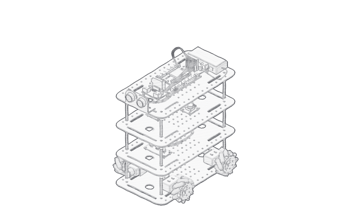
I would use the light sensor to obtain an ambient-light measurement (surrounding illumination), whilst the lights and buzzer could provide visible and audible feedback and the button could provide a local input. These components have the advantage of supporting individually inspectable behaviours, although combining them introduces additional wiring and control interactions. Hence, I would evaluate each module separately before examining their combined operation and power requirements.
A Servo-Mounted Distance Scanner
Second, the fixed front-facing sensor requires the rover to turn before measuring the distance to an obstacle on either side. I propose to place the HC-SR04 on a servo (position-controlled motor), allowing the sensor to rotate through a 180° sweep. This has the advantage of obtaining observations from several directions without turning the chassis, whilst requiring the servo position and the timing of each measurement to be coordinated.
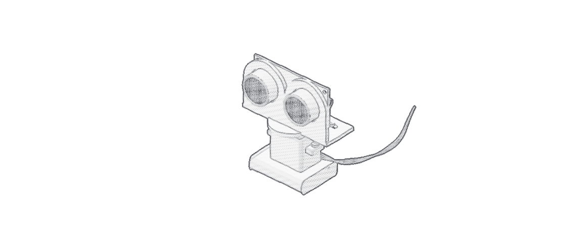
More precisely, I would associate each valid distance measurement with the corresponding servo angle (sensor orientation), producing a local set of direction-specific observations. However, these observations would be collected sequentially, so they would not represent the surroundings at a single instant, particularly when an obstacle is moving. I would therefore investigate the mounting alignment, settling time and echo quality before using the resulting observations to select a movement direction.
Camera-Based Scene Understanding
Finally, an obstacle-distance measurement provides information about proximity, but does not distinguish a pedestrian from vegetation or another obstacle (object category). I propose to add a DJI O4 camera above the distance sensor, with its images passed to a vision-language model (a model processing images and text). This could provide richer information about the surroundings, whilst requiring a video-capture and processing arrangement beyond the present ESP32 control system.
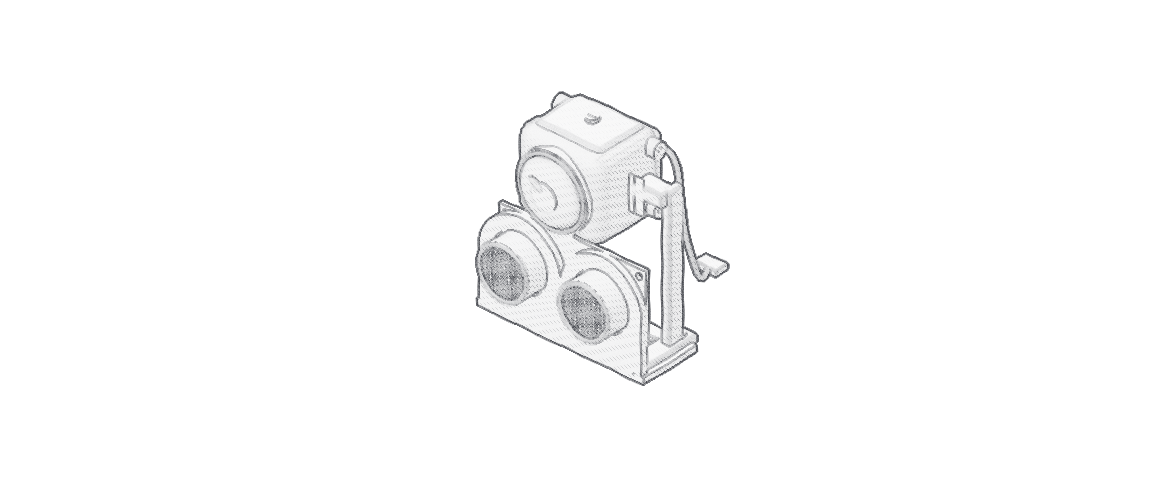
I would retain the distance sensor alongside the camera, since an interpretation of an image does not itself provide a verified stopping distance. The camera would contribute information about the scene (visual context), whereas the distance sensor would continue to contribute a local range measurement. This combination may support more informed decisions, whilst introducing processing delay (latency) and uncertain model outputs that the stopping procedure would need to handle explicitly.
Overall, I intend to extend the rover’s capacity to accommodate components, observe nearby obstacles and interpret its surroundings, with each extension evaluated against the specific requirement that motivated it.
By Peter Yuan,